In this tutorial, we’ll take a look at the Universal Asynchronous Receiver-Transmitter (UART), a simple communication protocol that can be used to get our microcontroller talking with radio transceivers (like WiFi and Bluetooth modules), personal computers, and all kinds of old electronic devices. Our goal for this tutorial will be to exchange data between our PIC and a computer. We’ll need a cheap circuit board called a USB-to-UART bridge for this tutorial, like this one — make sure you get one with a selectable 5V/3.3V. Make sure you read through the previous tutorial on communication protocols before getting started.
A quick note on the jargon: if we want to be technically precise, UART is a hardware device which performs communication, not a communication protocol. The proper name of the communication protocol UART devices use is “asynchronous serial” (sometimes just called “serial”), but this is a vague term and “UART” is widely used to refer to the protocol as well, so I’ll do it here. Also, UART is often simply called “serial” instead, but this is a bad nomenclature (ALL of the protocols we’ll be learning are serial protocols!), so please do not do this. I’ll be very upset if you do.
The Protocol
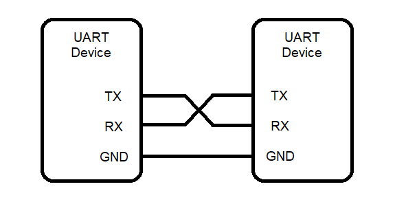
Before digging through the datasheet and trying to write code, let’s take a minute to understand how the UART communication protocol works. UART is a protocol used for low-speed communication between two devices. The devices are connected using two wires — one for sending data from A to B, and another for sending data from B to A. These are called “TX” (transmit) and “RX” (receive). Of course, the transmit pin on one device is connected to the receive pin on the other, and vice versa.
There’s always useful information in names, so let’s look at the acronym of our protocol. The ‘A’ in UART stands for “asynchronous.” Recall from the communication protocols article that “synchronous” refers to whether or not the protocol uses a clock signal to synchronize communication between devices. UART has no clock signal, so instead, it relies on “start” and “stop” bits to indicate when a transmission has started and ended.
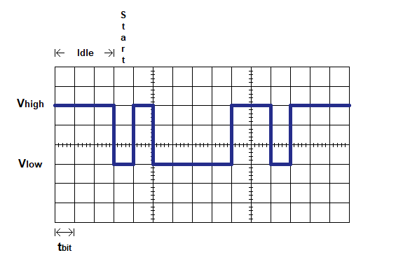
What does a UART word look like? When a device is idle (not transmitting), its TX pin is in the high state. When it’s time to send a byte, the TX pin goes low for a fixed duration called the bit length. This is the start bit. Then, the TX pin goes high or low depending on each bit, starting with the LSB — each state being held for the bit length. Finally, if optional stop bits are used, TX goes high for 1 bit length for each stop bit. Now the entire word has been transmitted and the line either goes high again (signalling that it’s idle again) or goes low to send the start bit for the next word.
Let’s look at a plot of a sample byte sent using UART, and try and decipher it. We’ll assume that each x-axis increment represents one bit length. What data is being represented by this signal?
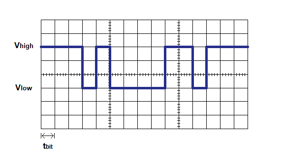
At the earliest time, the signal is in the high state, indicating that the device is idle — no communication is taking place. Then, the signal goes low for one bit length, which we know is the start bit.
Following the bit, we have the data word — let’s say it’s a byte — where the bits are sent in order from least- to most-significant bit. This is another way of saying that the bits are sennt in the opposite order of how we normally read them. After the 8 bits, we have the stop bits (if we’re using them), during each of which the TX line is high for 1 bit length. Then the byte is over, and the line either stays high to indicate that it’s idle again, or goes low for the start bit of another byte.
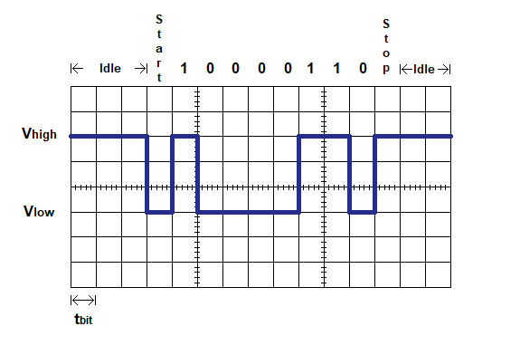
So what byte are we seeing? Reading the bytes in reverse order, we have 0110 0001, or 91 (0x61 in hex). If this is an ASCII character, we can Google an ASCII table, and we see that this character is the letter ‘a’. Good job!
Not all UART devices send and receive each word in the exact same way; different devices can use a variety of settings. For instance, some devices use 9 bits per word instead of 8. Another option is to use extra stop bits, or none at all. You might also encounter devices that use a special bit called a parity bit, which helps detect communication errors. These parameters are often given using a simple notation: in our example above, the notation for our configuration is 8N1 (8 bits per word, No parity bit, 1 stop bit). This is a very common configuration.
There’s one more crucial detail we skipped over: just how long is each bit length? In UART communication, the baud rate (symbols, or bits, per second) defines the time duration of each bit. For instance, if our communication uses 9600 baud (9600 bits per second), then the bit length is 1/9600 = 0.104 ms. The baud rate is a pre-agreed upon value that both devices know in order for the protocol to work — if you think the device you’re talking to uses one baud rate, but it actually uses a different rate, all you’ll read is garbage data!
Writing the code
By now, you’re pretty familiar with this part, aren’t you? The datasheet has a chapter for “EUSART”, a fancy module that performs both synchronous and asynchronous serial communication, and it’s the one we’re using. This micro has 2 EUSARTs, and we’re going to use EUSART1. Skim through the chapter. Unlike other chapters we’ve seen so far which have step-by-step instructions for configuring the module, the EUSART has several! We’ll look at the instructions for setting up the transmitter (33.1.1.7) and the receiver (33.1.2.8) in asynchronous mode. Summarizing, they tell us that we have to:
- Set up the GPIO pins (and PPS pin routing, if needed)
- Set some registers to give us the desired baud rate
- Enable the transmitter, receiver, and the EUSART module
We’ll start out by setting our I/O pin states: we’re going to use the PPS functionality to map the UART’s TX to RB7, and the RX to RB5. So we set RB7 as an output and RB5 as an digital input:
TRISBbits.TRISB5 = 0b1;		//set RB5 (RX) as an input
ANSELBbits.ANSB5 = 0b0;		//disable RB5's analog functionality
TRISBbits.TRISB7 = 0b0;		//set RB7 (TX) as an output
Then we’ll use the PPS module to route our peripheral to these pins. For the input, the datasheet tells us to use a register called RX1PPS, but the XC8 compiler thinks it’s an error (I’m pretty sure this is an error in the datasheet — yes, it happens!) and the actual register we want is called RX1DTPPS. If you’re curious, I’ll include a section at the bottom of the article about errors in datasheets. Looking at the PPS output section, we’re also told that the value for the TX pin’s output is 0x0F, so we’ll assign that value to RB7PPS:
RB7PPS = 0x0F;			//route TX1 to RB7
RX1DTPPS = 0x0D;		//route RB5 to RX1
Next we’ll write some code to select a baud rate. The instructions for setting up the transmitter point us to section 33.3, “EUSART Baud Rate Generator”. We need to compute the values for the SPxBRGH and SPxBRGL register pair, and we’re given a formula which we can use to do that:

However, make sure you read the section on the baud rate generator — there are a few gotchas we need to be aware of. The BRG can be configured to operate in 8-bit mode or 16-bit mode, and if we use 8-bit mode, then we’re not using the full register pair, only SPxBRGL. Also, the 64x multiplier has several possible values. Section 33.3 has a link to a table, Table 33-3, which tells us which bits to use to give us a multiplier of 64x, 16x, or 4x.
How do we select a multiplier? Let’s assume we want the 64x multiplier, and try out some calculations. The 2 most common baud rates devices use are 9600 baud and 115200 baud. If we use 9600 baud, we get the following computation:

No worries here! But let’s try the same calculation with a baud rate of 115200:

There’s a problem here, since this value will get rounded down to 3 — quite a bit of rounding error. If we plug this back into the original formula, we’ll see what baud rate we’d actually get:

That’s not even close! This has an error of almost 9%, and we’ll have lots of problems trying to read and write data. Instead, let’s try with a 16x multiplier.


Now the rounding error is much less severe. Note that both of these values are less than 256, so we can use the 8-bit baud rate mode. Table 33-3 indicates that if we want this mode, and we’re using the 16x multiplier, we need to set BRG16=0 and BRGH=1. The register maps below tell us that these bits belong to the BAUDxCON and TXxSTA registers, respectively.
BAUD1CONbits.BRG16 = 0b0;
TX1STAbits.BRGH = 0b1;
We can use our formula to automatically calculate the appropriate value for SPxBRGL, where we can reduce  to 2,000,000:
SP1BRGL = 2000000/baud - 1;
Now we just have to set our EUSART module into asynchronous mode with 8-bit transmission, and enable the transmitter, receiver, and the module as a whole. Let’s write our setupUART() function.
void setupUART(unsigned long baud)
{RB7PPS = 0x0F; //route TX1 to RB7
RX1DTPPS = 0x0D; //route RB5 to RX1
//set up transmitTX1STAbits.TX9 = 0b0; //8-bit transmission
TX1STAbits.TXEN = 0b1; //enable the transmitter
TX1STAbits.SYNC = 0b0; //async mode
//set up receiveRC1STAbits.RX9 = 0b0; //8-bit reception
RC1STAbits.CREN = 0b1; //enable the receiver
//set up baud rateBAUD1CONbits.BRG16 = 0b0; //8-bit baud rate generator
TX1STAbits.BRGH = 0b1; //high baud rate (with BRG16=0, gives a 16x multiplier)
SP1BRGL = 2000000/baud - 1; //calculate the correct baud rate value
RC1STAbits.SPEN = 0b1; //enable the serial port
}
With the module all configured and taken care of, we need some functions to read and write to our serial port. First we’ll create a function that can transmit a single character. From reading the first few pages of the chapter (or the register maps), we learn that transmission is performed by writing a byte to the TXxREG register. That’s it — just set TXxREG to the value and its bits will be shifted out to the TX line. We also learn that the TRMT bit of the TXxSTA register is equal to 0 while a transmission is taking place, and 1 when the transmit shift register is available. So we’ll need to check this bit before writing to the transmit register:
void writeUARTchar(const char byte)
{while(TX1STAbits.TRMT == 0); //wait until the transmit shift register
//is emptyTX1REG = byte; //send the byte
}
Our code’s ready to start testing. Grab your USB-to-UART bridge and make the following connections before plugging it in to your computer:
- VCC to VCC
- GND to GND
- TX to our microcontroller’s RX (pin RB5)
- RX to our microcontroller’s TX (pin RB7)
You’ll also need a serial terminal installed on your machine to talk to the bridge. If you’re a Windows user, Tera Term is a great option. If you run a Linux distro, Minicom is one available terminal. Whatever terminal you end up using, look up how to configure it for 9600 baud.
Let’s write a simple main() function to test out our writeUARTchar() function. We’ll include our setupTimer0() and delayMs() functions from the previous timer tutorial.
void main(void)
{setupGPIO();
setupTimer0();
setupUART(9600);
while(1)
{writeUARTchar('h');
writeUARTchar('e');
writeUARTchar('l');
writeUARTchar('l');
writeUARTchar('o');
writeUARTchar('\r');
writeUARTchar('\n');
delayMs(1000);
}}
If everything is set up correctly, you should see “hello” print to the serial terminal once every second. If not, re-check your connections (remember, TX goes to RX, and vice versa!) and take a look at the troubleshooting section.
We can transmit UART data! So far, it’s pretty tedious to use, though — so let’s add a function to print entire strings to make our life easier!
void writeUARTstring(const char *str)
{for(const char *cptr = str; *cptr != '\0'; cptr++)
writeUARTchar(*cptr);
}
Now we can easily print messages to the UART terminal. Let’s update our main() function to test it out:
writeUARTstring("program starting now!\r\n");
while(1)
{writeUARTstring("LED on!\r\n");
LATCbits.LATC0 = 0b1;
delayMs(1000);
writeUARTstring("LED off!\r\n");
LATCbits.LATC0 = 0b0;
delayMs(1000);
}
Take a look at your serial terminal and you should see the messages printing as the LED turns on and off.
Reading UART data
Just like the TXxREG register, we can read data received by the UART module from the RCxREG register. The datasheet tells us that every time a character is received, the RCxIF bit is automatically set — so we can check this bit in our loop. However, this isn’t a great way to handle reading UART data. Why? This technique of constantly checking for an event to occur (called polling) usually isn’t a good way to react to external events; since data isn’t being received often, most of the checks to see if RCxIF is set are just wasting clock cycles. We’ll cover a better way to read a stream of UART data in a future tutorial on interrupts. For now, our readUARTbyte() function can simply return the received value:
char readUARTchar(void)
{
	return RC1REG;
}
Now we can poll the RCxIF bit in our main() loop:
while(1)
{
	if(RC1IF)
	{

		char c = readUARTchar();
		writeUARTstring("input detected, read char: ");
		writeUARTchar(c);
		writeUARTstring("\r\n");

		if(c == '1')
			LATCbits.LATC0 = 0b1;
		else if(c == '0')
			LATCbits.LATC0 = 0b0;

		RC1IF = 0b0;
	}

}
By entering the character 1 or 0 into the terminal, we can turn our LED on or off! This is a simple example, but it’s easy to see how we can use a serial terminal to control more complex devices. Take a look at the next article to learn SPI, an even more powerful communication protocol
Going Further
Can we do more with UART that control a little LED? Of course! Here are some things to try out:
- Lots of communication modules use UART, such as WiFi modules (like the popular ESP-01, or if you’re looking for something more powerful/serious, try the RN4870/1) and Bluetooth modules. Pick one, buy it, and take a look at a datasheet to see what UART commands it responds to.
- Our writeUARTstring() function is definitely easier to use than calling a function for each character, but what if we wanted something more flexible? See if you can write a printf() implementation that accepts format specifiers (%c, %s, %d…) to write to the UART port.
Troubleshooting
Having serial port troubles? Here are some things you can try to identify the problem:
- First, let’s make sure that your terminal is even able to display text. Disconnect your USB-to-UART bridge from the microcontroller circuit and directly connect the TX and RX pins with a jumper. This is called a “loopback”. Now type on your keyboard, and each character that’s sent out the TX pin is read on the RX pin. The keys you’re typing should show up in the terminal. If not, your terminal isn’t working at all — look around online to figure out how to use it.
- Write a quick program that calls writeUARTchar() or writeUARTstring() over and over again in a loop. Take a look at the USB-to-UART bridge — it has a LED that’s connected to the RX line, so if it’s receiving any signal, the LED will flicker. Is it flickering?
- If the LED is flickering but nothing is printing in the terminal, you’re sending the UART bridge a signal, which means that either you’re sending the wrong signal (your baud rate may be way off) or you’re sending the right signal, but something is misconfigured in your terminal settings.
- If it’s not flickering, either you’re not sending a signal at all (which means something is wrong with your code — maybe part of the UART isn’t enabled, or the PPS routing is wrong, or a pin TRIS bit wasn’t cleared), or there’s a electrical connection problem (make sure that TX is connected to RX and vice versa).
- If you’re seeing garbage data in the terminal (weird ASCII characters), there’s a good chance your baud rates don’t match up. Either your microcontroller’s baud rate isn’t 9600, which means there’s a problem with your code, or your terminal’s baud rate isn’t 9600. Also, make sure your terminal is set up for 8N1 (8-bit words, no parity bit, 1 stop bit).
My datasheet’s fallen and it can’t get up!
What do you do if your datasheet has a mistake?! First off, if you’re anything like me, 99% of the time, it isn’t really a mistake — you just screwed up somewhere. However, people make mistakes, and datasheet errors do happen. Unfortunately, Googling around often won’t help (you’ll search for a problem with one specific model and find similar problems with other microcontrollers, which won’t help). Here are some things you can do if you suspect that a datasheet has an error:
- Check the errata — a special document that describes errors in a given version of a datasheet — might have the answer. You can find datasheet errata on the manufacturer’s website. Here’s the errata for the PIC16F15345.
- With the problem I encountered (the datasheet said there’s a register called RX1PPS, but my compiler — which is the latest version — calls it an error), the solution was to dig into the code. The #include <xc.h> at the top of our program automatically includes the header file for our microcontroller, pic16f15345.h, which is where RX1PPS should have been defined. Searching through this document , I found that “RX1PPS” was not in the document, but the similarly-named “RX1DTPPS” was (and it turned out to be the correct register).
- If all else fails, submitting a help ticket to the company that makes the microcontroller is always an option.