In this article we’ll cover how to build a circuit with a microcontroller on a breadboard so that we can start programming. Breadboarding is a great way to get started with microcontroller design — it’s flexible, so as you get new ideas for stuff you want to try, you can easily experiment with interfacing different devices to your microcontroller. However, if electronics isn’t your strong suit, you might be better off buying a dev board. If you’re worried about how much everything will cost, don’t be — I’ll suggest a few cheap options for getting all the parts and equipment.
Let’s start by identifying what we’ll need to power, program, and run code on a microcontroller:
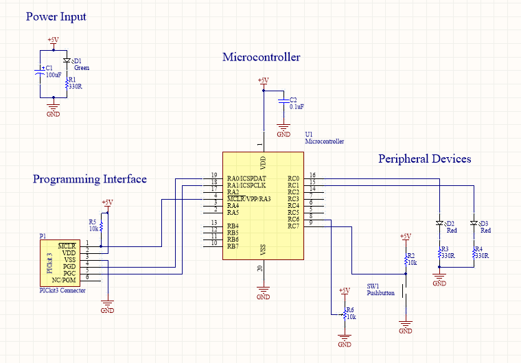
- A microcontroller! We’ll be using the PIC16F15345, a 8-bit MCU. We’ll need a DIP part to go into our breadboard, so get one like this. Follow the link to the Digikey listing and look for the microcontroller’s datasheet — it’s a monstrous 500+ pages, but don’t worry, I’ll show you where to look.
- A power supply. Typically, PIC MCUs with “F” in the name run off 5V and those with “LF” are the low-voltage models and run off 3V. If we look at the 1st page of the datasheet, the “Operating Voltage Range” section lists the supply voltage as 2.3V to 5.5V, and we’ll be powering the controller off 5V. You could use a bench power supply (if you have one), buy a breadboard-mount power supply, or use a regulator to step down a higher DC voltage. If you don’t have any of these and you’re itching to get started, you can also power the circuit from the PICkit — I’ll discuss this more below.
- An oscillator. There are several ways to do this — a crystal resonator is often used — but we’re going to use a RC oscillator that’s internal to the microcontroller to make our lives a little easier.
- A programming interface. This just consists of wiring certain pins away from the MCU, plus a couple resistors and caps.
- Signal conditioning. We’ll want a decoupling cap to filter noise on the supply line.
- Stuff to control. We’ll put a couple LEDs that can be controlled by the microcontroller and a pushbutton that can be read. Of course, feel free to put anything else you’d like to experiment with!
- Of course, we’ll also need a breadboard and some solid gauge wire (24 gauge is a good choice) or jumpers to connect everything.
I’ll include a section at the end of this article about buying materials if you’re not sure what to get.
One other thing to point out is that you can also power your microcontroller and associated circuitry from the PICkit, which I’ll show you how to do in the next tutorial. However, this isn’t a great solution and can cause programming errors — especially if you have anything in your circuit that draws substantial current — so I’d recommend that you only resort to this if, say, your power supply is in the mail and you’re itchy to start programming.
The circuit
In order to figure out how to connect everything, we need to look at the datasheet. Scroll down a bit and we’ll find the “Pin Diagrams” section, starting on page 5; this shows us the pinouts of the microcontrollers described in this datasheet. Recall that the name of the datasheet is “PIC16(L)F15325/45”, and that it details multiple different datasheets in different packages — this is something to watch out for, or you’ll end up using the wrong data and the design won’t work. In our case, we’re using the PIC16F15345, and the part we have picked out on Digikey is listed as a 20-pin DIP package. The second pin diagram on page 5 is the correct micro and package/number of pins, so that’s the one we’re looking for.

Other than the power/ground pins, the only connections to specific MCU pins we’re concerned with are the programming interface. We’ll be programming the controller using a technique called In-Circuit Serial Programming (ICSP): instead of programming the microcontroller outside of the circuit (and removing it every time we need to re-flash it), we can program it in the circuit. Sweet!
To program our PIC using ICSP, we’ll need VDD/VSS and 3 other pins. Program Data (ICSPDAT, often labeled as PGD) and Program Clock (ICSPCLK, often labeled as PGC) are used to transfer the data to the micro. MCLR also needs to be connected. This gives us 5 programming pins in total, which we’ll connect to using our PICkit (pin 6 on the PICkit is used for a special programming mode and can be left disconnected). Note that these pins are in a specific order — MCLR must go to pin 1 of the PICkit, VDD must go to pin 2, and so on.
After you’ve connected everything, power up the circuit and the green indicator LED should turn on. If it doesn’t, disconnect power and re-check all your connections. Once you’re sure everything is connected, we can move to the next step: writing some code to push onto the MCU.
Where to buy stuff
If you don’t have a breadboard, you can get one on Amazon or Ebay — they’re cheap. This is also where you’d get solid-core wire or jumpers to connect everything. If you’re going with the breadboard-mount power supply option, note that some vendors offer a combo deal where you can get breadboard, jumpers and power supply all together (search for “Arduino kit”).
I’d also suggest that you buy a multimeter, which will be very helpful in testing and debugging our circuit throughout the tutorials. As recommended by Dave Jones of EEVblog (a video blog that you should absolutely check out if you haven’t done so already), this multimeter is only $26 and performs decently as compared to higher-end models.
For the parts, take a look at the attached Bill of Materials. I’ve included part numbers from two different websites — Digikey and Tayda Electronics. Digikey is the more professional website, and the parts have better documentation, but Tayda’s components are much cheaper. Note that a few of the parts aren’t available from Tayda (such as the microcontroller), so if you’re trying to go the cheaper route, you’ll have to place orders with both websites — it’s up to you.