In this tutorial, we’ll learn exactly what a peripheral is, what a GPIO pin is, and we’ll write some code to turn on some LEDs. Before you start this tutorial, you’ll need to have a microcontroller on a board or breadboard that’s ready to program, a programmer, and the IDE all set up. I’ll also assume you know how to program in C, at least at a beginner level.
Before we look at the code, let’s briefly talk about the structure of a microcontroller. A micro contains a processor, memory, and peripherals. But what exactly is a peripheral (also called a module)? Peripherals are just circuits inside the micro. They do a variety of functions, like controlling external devices, communicating with other processors, and generating timing and alert signals for the CPU.
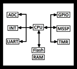
The GPIO module, or “General Purpose Input/Output” module, is a circuit that can function as either an digital output (which generates a high or low voltage) or as a digital input (which reads a high or low voltage). We can use a GPIO module to output a voltage on a pin that’s connected to a LED, turning the LED on or off.
The code
Ok, enough theory. Let’s dive in and write some code, and then we’ll analyze it. Put the following code in your main() function, build it like we learned in the previous tutorial, and program it (remember, we use the button with the downward green arrow to push code to the microcontroller):
void main(void)
{TRISCbits.TRISC0 = 0b0; //configure pin RC0 as an output
LATCbits.LATC0 = 0b1; //set pin RC0 state to high
while(1); //wait forever
return;
}
If everything is set up correctly, the LED connected to pin RC0 (pin 16 if your circuit is set up on a breadboard) should light up, and the other LED should be off. Note that this firmware is now programmed in non-volatile memory — if you power-cycle the MCU, the program will still be stored.
How does this work? In the CPU, there are registers — some are general-purpose and some of them are special function registers (SFRs). Many of the SFRs are used to control peripherals, and do things like turn a peripheral on or off, set and query its status, and so forth. In microcontroller programming, everything you do is based on accessing peripherals, which is done by writing to and reading from SFRs. Anytime we want to blink a LED, read from a sensor, set a timer, or just about anything else, we’ll do it via one or more SFRs that control peripherals.
Our code accesses two SFRs:
- TRISC is the SFR that controls the GPIO states for port C (similarly, TRISA controls states for port A, and so on). Each bit sets the state for one of the pins in the port. Setting a bit to a 0 makes the associated pin an output, and setting a bit to 1 makes the associated pin an input. In our code, we set bit 0 of TRISC (the bit corresponding to pin RC0) to 0, setting that pin as an output.
- LATC controls the state of the output pins for port C — if a given pin in port C is already an output pin (i.e. its TRISC bit is 0), then setting its LATC bit to 0 makes it go low (its voltage is set to VSS) and setting it to 1 makes it go high (its voltage is set to VDD).
Let’s go back and revise our code to turn on the second LED on pin RC1, and explicitly turn off the first LED:
void main(void)
{TRISCbits.TRISC0 = 0b0; //configure pin RC0 as an output
TRISCbits.TRISC1 = 0b0; //configure pin RC1 as an output
LATCbits.LATC0 = 0b1; //set pin RC0 state to high
LATCbits.LATC1 = 0b0; //set pin RC1 state to low
while(1); //wait forever
return;
}
Simple stuff. There are two different syntaxes that we can use to access a SFR like LATC. When we use the LATCbits.LATC0 syntax, we’re treating LATC as a struct, where the struct fields are the bits. But we can also treat the entire LATC as a single variable, and set the whole thing at once. For example:
LATC = 0b11110000;	//sets bits 0-3 to logic low, and bits 4-7 to logic high
LATC = 0xF0;		//same thing, but using hexadecimal representation
TRISC |= 0b00001100;	//uses bit masking to set bits 2 and 3 (making them inputs), leaving the other bits unaffected
Knowing this, we can light both LEDs using bit masking like this:
void main(void)
{TRISC &= 0b11111100; //clear bits 0 and 1
LATC |= 00000011; //set bits 0 and 1
while(1); //wait forever
return;
}
There’s one last point we need to cover about digital outputs. Microcontrollers are smart, but they’re not very powerful, electrically speaking — a GPIO pin can only sink or source so much current, usually less than 10mA. If you’re trying to control a device that runs off more current than that (such as a higher-powered LED or a DC motor), don’t power it directly from the GPIO pin! If you’re lucky, you’ll only fry that particular GPIO module, but you might destroy your MCU. Instead, use a N-channel MOSFET — which uses the small current from the micro to control a higher current from the power supply — or a relay.
Continue to the second part of the GPIO tutorial.
Going further
Besides LEDs, what else can we turn on and off with a I/O pin? Lots of things!
- DC motors
- Solenoid valves (build a paintball gun!)
- Heating elements
- Basically, anything that’s always fully on or fully off
Troubleshooting
If you can’t program the microcontroller at all, take a look at the troubleshooting section at the end of my previous tutorial on setting up the IDE — it covers most of the problems that may occur when you can’t push code on to the micro. If that doesn’t fix the problem, double-check all your wiring. If you’re powering your circuit from the PICkit, I’ll reiterate that this isn’t a great idea and that you should consider using a breadboard power supply, a dedicated PSU (if you have money to drop), or a battery powering a 5V regulator.
If you’re able to program the microcontroller but the LEDs don’t light, check to make sure that the LEDs are in the right way — if you look at one of them head-on, the flat side is the cathode (it may also have a shorter leg), which is the pin that connects to the lower voltage. Also, make sure that the LED circuit is connected to the correct pin number on the microcontroller.