This tutorial will get you set up with MPLAB X, the IDE we’ll be using to develop our firmware. If you haven’t already done so, go ahead and install both MPLAB and the XC8 compiler for 8-bit microcontrollers. Also, if you don’t already have a microcontroller ready to program, take a look at my article on how to set that up.
Setting up the IDE
Before we can start writing any code, let’s configure some settings for the IDE. Open up MPLAB and go to Tools > Options. In the wizard that pops up, click the ‘Embedded’ icon, then make the following changes:
- In the “Generic Settings” tab, set “Debug startup” to “Halt at Main”.
- In the “Build Tools” tab, select XC8 as our toolchain (if it’s not there, you may have to add it).
Now our IDE’s all ready to use. Let’s go ahead and make a project. Click on the “New Project” icon near the top-left or go to File > New Project.
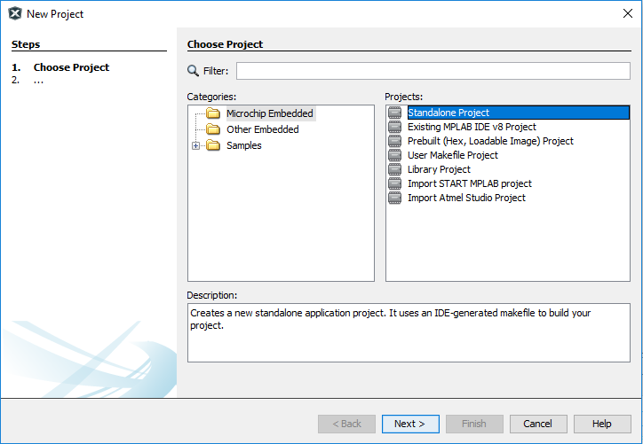
Select a “Standalone Project” — we want to build from the ground up. Next, enter the name of the device you’re using — if you’re following one of the previous tutorials on hooking up your own microcontroller circuit, you’d enter PIC16F15345. Next you’ll be asked for the programming/debugging tool you’re using, which is the PICkit 3, and the compiler toolchain, which is XC8. The last step is to give your project a name and location, and we have a new project.
A first look at MPLAB
Before we configure our project, let’s take a second to get familiar with a few of the features (and idiosyncrasies) of MPLAB X.
On the top of the application we have some buttons we’ll be using a lot:


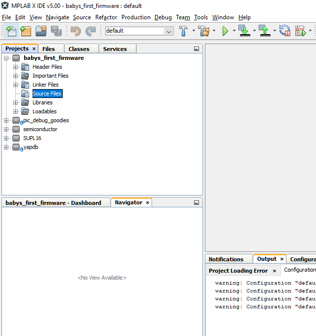
On the left of the application, we have a list of projects in our workspace. I wanna take a second and point out something that will mess you up if you’re not careful — scroll up and take a look at my projects. See how the first one (“babys_first_firmware”) is listed in bold? That means it’s the active project. When you use the compile/program/debug buttons, the active project is the one that gets targeted — which means that the files you’re editing could NOT be the ones that get compiled! Annoying, right? You can change this by right-clicking on a project you want to work on and selecting “Set as Main Project”.
Configuring your project
Let’s add a few files to our project. In the project view, right-click on “Source Files”, then navigate to New > main.c. Call it “main” (who the hell uses newmain?) and create it. A few lines of code will be auto-generated — don’t be outraged by the use of void main(void) instead of int main(void), as this is correct for a microcontroller (since there’s no operating system or runtime environment to return a int to). Also, make sure that the autogenerated code has #include <xc.h> and not the device specific header (i.e. #include <pic16f15345.h>).
Before we move to the next step, let’s try and compile our project and make sure everything’s okay so far. Click the hammer+broom icon and wait for the output messages on the bottom to scroll. If you see CLEAN SUCCESSFUL followed by BUILD SUCCESSFUL, you’re good to keep going.
Next, we’ll set the microcontroller’s configuration bits. These set the status of various microcontroller features, such as the way it gets programmed, memory protection, and much more. We want these in a separate source file, so right-click on Source Files and go to New > C Source File. We’ll call the new file “config.c”. Once you’ve created the file, we need a list of configuration bits for our microcontroller. Go to Window > Target Memory Views > Configuration Bits, and a table will appear at the bottom of the program. We need to change just a few of these:
- The RSTOSC field bits “determine the type of oscillator that will be used when the device reset, including when it is first powered up” (from the datasheet, Oscillator chapter, p. 103). We want to use an internal oscillator, so set this field to HFINT32, which runs the internal oscillator at 32MHz.
- The WDTE field sets the operating mode of the watchdog timer. We’ll disable that for now, so set this field to OFF.
- LVP toggles a special low-voltage programming mode which uses all 6 pins on the PICkit. Instead, we’re going to use the 5-pin mode, so set this to OFF.
With all the appropriate configuration settings, click the “Generate Source Code to Output” button, which will generate a bunch of preprocessor directives that set our configuration bits. Copy these and paste them into config.c. Save the file and build the project; once again, we should clean and build successfully.
If you’re using the PICkit to power your circuit, we need to set that up. Right-click the project name and go to “Properties”, all the way at the bottom. On the left, select the “PICkit 3” menu. Then open the drop-down and select “Power”. Check the box to enable power from the PICkit, and set the voltage level to the level you’re using.
Now let’s try and connect to our microcontroller and upload a program. Of course, we haven’t written anything, but we’ll find out if everything’s set up correctly. Plug in your PICkit to your computer, then connect the 6-pin connector to the programming interface on your board. Make sure that the pin 1 indication on the PICkit matches pin 1 on your programming interface. Turn on your power supply (if you’re using one), then press the “Make and Program” button — remember, that’s the icon with the green downward-facing arrow.
After a minute or so, you’ll see a message indicating that the program was successfully written. You’ve set everything up correctly! You’re all ready to learn how to light up those LEDs.
Troubleshooting
Got an error message trying to push code to your PIC? See if one of these paragraphs describes the error you were given.
If your error says that the target voltage was not detected, make sure that the power supply you’re using is on (if you’re using an indicator LED, it should be on). If it is, cut power and re-check your PICkit connections — make sure that the right signals are going to the right PICkit pins (i.e. pin 2 must be connected to VDD), and that the MCLR/PGD/PGC lines are going to the right microcontroller pins. Also, check the rest of your connections and make sure that power and ground aren’t being shorted together (test it with a multimeter if you have one).
If you get an error saying that the Device ID could not be found/ doesn’t match, lots of things could be wrong. Check the PICkit connections as described in the previous paragraph. Check the project properties (right-click the project and go to “Properties”, and you’ll see the device number — make sure that this matches the PIC you’re using. If you have multiple projects in MPLAB, make sure that the one you want is set as the main project (its name should be bold). Extra length on connections between your programmer and your microcontroller can also cause problems, so try shortening the wires connecting the PICkit to the breadboard (or removing the 6-pin jumper, if you’re using it, and connecting wires directly to the PICkit).
If you’re powering the circuit from the PICkit, you might see an error message that says that it cannot supply enough power. The first thing you should do is cut power and check all your breadboard connections to make sure that nothing’s shorting power and ground together. Assuming your circuit is fine, switching to using a separate power supply is the likely fix.