In this tutorial, we’re going to learn about the fundamentals of communication protocols — the languages that microcontrollers use to talk with each other and with other electronic devices. Once we understand the concept of a communication protocol, we’ll be able to exchange data between our PIC and our computer, interface with WiFi and Bluetooth modules, and read from memory devices like SD cards and flash chips. But before we can start writing code to communicate, we need to understand exactly why we need these protocols and how they work.
What is a communication protocol?
When we use a microcontroller to light a LED, we might sometimes say that the microcontroller pin is “outputting a 1” or “outputting a 0”. Recall, however, that this is an abstraction — what’s really happening is that the pin is being set to some voltage (5V or 0V). Similarly, when our microcontroller is communicating, we’ll say that the microcontroller is “sending a byte”, or “reading a string”. But how exactly does this happen? Again, the microcontroller is just writing and reading voltages — so we need to understand the nuts and bolts of how a sequence of voltages gets translated into bytes of data.
Let’s illustrate this with an example. Suppose that some device A is sending data to device B. These could be any devices: two computers, chips on a circuit board, it doesn’t matter. We use a measurement tool that plots the signal over time (an oscilloscope) to look at the signal and try and determine the sequence of bits being sent.
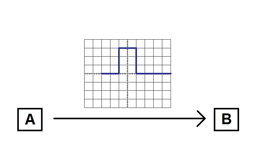
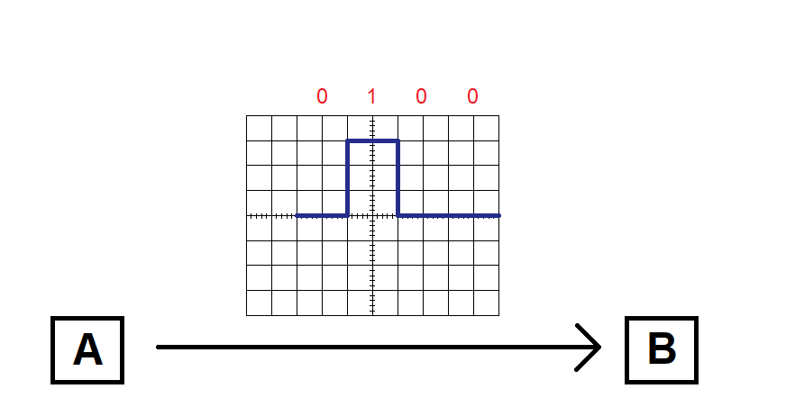
Looking at this signal, it may appear that “0100” is the correct sequence of bits being transmitted:
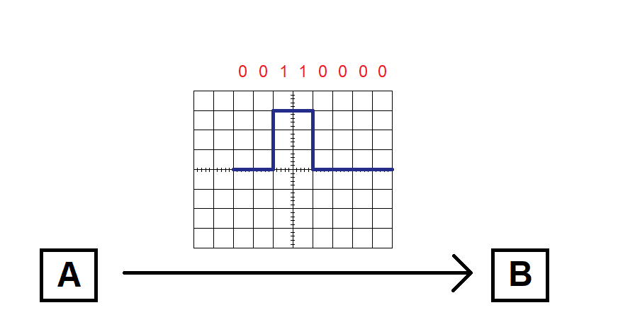
However, this interpretation is based on a few assumptions. For example, we assumed that there’s a bit for every two grid divisions on the graph (in other words, that the signal is sampled at a certain bit rate). But what if the signal is actually sampled once for every division? Then we’d read twice as many bits, and we’d interpret the data as “00110000”.
Of course, the sampling rate could also be 3 times our original assumption (in which case the sequence would be “000111000000”), or 4 times, or anything.
Similarly, how do we know that the data starts on the left of the plot? In fact, how do we know when any communication starts? If we measured the voltage being sent by device A and we saw a constant 0V, is the device sending “0000…”, or is it simply waiting between transmissions? Maybe the first pulse is a “start bit” — it’s not really part of the data, it’s just indicating the start of the transmission — in which case only the signal after this start bit would be considered actual data:

So sending data isn’t as trivial as “just send the bytes”, as any signal can be interpreted (reasonably) in several ways. Now let’s consider a scenario where before I asked what the bit sequence was, I defined some rules about how you should interpret the signal. For example, I could say that the signal begins with a “start bit” of a given duration, and that we should sample the signal once every two divisions. Now we can correctly read the signal, and interpret it correctly. This collection of rules that defines the meaning of our signal is a communication protocol.
Pick a protocol, any protocol
Can you think of different rules that we can use to define our signal? There are many different ways to send data between devices, each with their own advantages and drawbacks.
- Synchronous vs. Asynchronous: instead of having just one connection between A and B (on which our data is transmitted), we could have 2 connections — the second connection would go high every time the next data bit is ready to be sampled. This would “synchronize” the communication by telling B when to read each bit, and would eliminate the need for a pre-defined sampling rate. This would be more reliable, as B can’t sample at the wrong time, also enabling faster data transmission. However, this also requires an extra pin on each device.
- Half-duplex vs. Full-duplex: what if A and B are both sending data to each other? In a half-duplex protocol, only one device can talk at a time, while full-duplex protocols allow simultaneous transmissions from both devices. However, this isn’t free, as it also requires additional pins (one line is needed for each direction).
- Addressed vs. Non-addressed: what if there are more than 2 devices? Addressing is one way to resolve this problem — each device has a “name”, which can transmitted to indicate who’s talking to who — but this adds lots of complexity to the protocol and slows down communication.
- Serial vs. parallel: in our example, the data bits are sent sequentially, one at a time (serially). If sending each bit takes n microseconds, then sending a byte takes 8*n microseconds (or longer, if start bits or other special bits are used). Instead, we could use 8 different lines to connect A to B, and send each of the 8 bits in the byte on a different line (in parallel). This is 8 times faster, but uses 8 times the number of pins — and we usually don’t have too many of those, so most communication protocols used by microcontrollers are serial protocols.
In general, different protocols are useful for different applications. Nothing is free — some protocols might be faster or have extra features, but at the expense of using extra pins or added complexity. By understanding the differences between communication protocols, we can choose the best one for the job.
Lots of communication protocols are used by microcontrollers, but 3 are much more common than the rest: UART, SPI, and I2C. Almost all microcontrollers have dedicated peripheral modules for using these protocols. The next few articles will cover how each protocol works and how to configure the modules to communicate according to their rules. We’ll start with the UART protocol.